Before I write this post on Moment of Inertia, I must admit, I have always been very poor at the subject. Even as an engineering student, the last subject I was ever interested in was SOM (Strength of Materials) or how most of us call it these days, Solid Mechanics. And ironically today I am writing a post on something from the same subject.
Anyways, coming back to the very much intended topic, what is moment of inertia? and how does it matter?
But before we jump on to Moment of Inertia, it will be wise to understand Inertia. In layman terms, inertia is nothing but resistance offered by a body to maintain its position/speed against an external force applied on it. Or say the tendency of a body to remain unchanged.
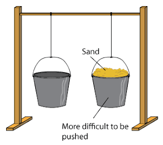
For instance, in the above picture, it is harder to push the bucket filled with sand compared to the empty one because it has got more mass. More mass means, its resistance to any external force is comparatively more, which means it has got more inertia, and that's all it is, or we can also look at it as an internal resistive force against an external force.
This is also covered by Newton's 2nd laws of motion, which says more or less the same thing, bigger is the mass, greater is the force required to move it.
 | |||||
| Another very self explanatory example of Inertia |
The above example not just sets another perfect explanation for inertia but on a different subject also tells us why proper load binding is so important on commercial vehicles and also how important the front wall design is on truck/trailer bodies. Anyways, now when we are clear about Inertia, lets look into Moment of Inertia. Like inertia is the resistance to an "linear" external force, Moment of inertia is the resistance offered by a body against an external rotational force applied on it about an axis and hence is also known as the rotational inertia.
By formula, Moment of inertia depends upon mass of the object and its distance from the rotational axis. More is the mass and farther it is from the rotational axis, more is the moment of inertia and hence more external force, or we can say more torque is required to move it.
But moment of inertia also depends on another factor, i.e. shape of the body or we can say, the way the mass is distributed. The shape of the body makes a big difference to the moment of inertia value. For instance, in the following picture, in both the cases, the mass of the person and the axis of rotation is the same, but in the first case, the mass is distributed away from the axis of rotation while in the second case, the mass is confined around the axis. Hence the moment of inertia is comparatively more in case one, and therefore more external force is required to rotate it.
Now, considering I have explained the term, I would like to clarify something here, as I have heard too many people misunderstanding it.
"Moment of inertia of a body doesn't tell us by itself how much load or force it can withstand, before it fails. It only tells us how much the body can resist the external force. Even by formula, we saw that it is a property of a body governed by its mass, shape and distance from the rotational axis. External loads are not used to calculate moment of inertia of any body."
Having said that, on the same time, it is useful when we calculate bending moments acting on a beam, which further tells us if the beam will be able to withstand the loads or not.
For instance, say I want to design a truck body and plan to design the base frame using I beams. Now, I don't want to use very heavy I beams, for it will reduce the payload capacity of the truck, hence, I need to know the exact size of the I beams I should go for, for the given pay load. Say I selected a 6"x8"x1" I beam. But the analysis tells me that the beams will fail against the given pay load. Which means, I need to go to a bigger I beam. But what size to go to? Say
hypothetically, just for the sake of understanding the subject better, I
instead of looking for another alternative or jumping to the next size
of the I beam, I plan to get a custom I beam made to suit the application. But what should be the size? And that's where moment of inertia comes into the picture.
We can see from the above equation that Moment of Inertia of a body is inversely proportional to bending stress (acting on the body due to the external loads). So if we increase the moment of inertia of the beam, it further increases its load carrying capacity. Now where do we add more material?
As shown in the above picture, say I start by adding one square inch material to the I beam to have a better moment of inertia. As shown in the above picture, the first option gives me the greatest value, while adding the same amount of material somewhere else on the same beam gives comparatively poorer results. And hence, if an increase of 33.5% in the moment of inertia enables the beam to withstand the given loads, I would say I have got the optimum design solution.


